Real-World RL with GimArm#
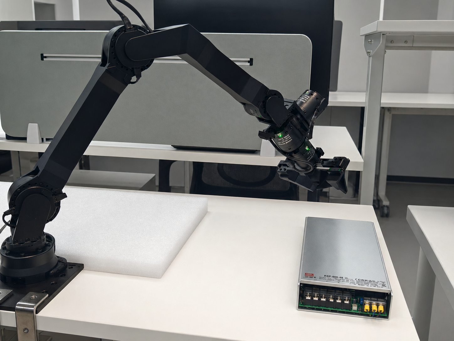
GimArm 6-DoF arm used for SocketCAN control, motor calibration, and peg-insertion training.#
Run RLinf on a GimArm 6-DoF arm over SocketCAN. You will install the CAN control SDK, calibrate motors, set a target end-effector pose, collect demonstrations, and launch real-world training.
Overview#
Train a real-world peg-insertion policy on GimArm with CAN-based control.
CNN policy
SAC · RLPD
Peg insertion
GimArm · CAN FD · gripper
gim_arm_control SDK.Tasks#
Task |
Config / entry point |
Description |
|---|---|---|
Hardware check |
|
Verify controller launch, state reads, motion, reset, and gripper commands. |
Data collection |
|
Collect VR teleoperation demonstrations. |
Training |
GimArm real-world config |
Train on the peg-insertion task with target-pose reward. |
Observation and Action#
Field |
Description |
|---|---|
Observation |
Camera frames plus GimArm joint/TCP state. |
Action |
6-DoF arm control with gripper command, depending on config. |
Reward |
Sparse or dense FK distance to |
Prompt |
Peg-insertion task text in the env config. |
Hardware Setup#
Warning
Ensure the controller node and the training node are in the same local network. The GimArm robot is connected to the controller node via CAN bus, not Ethernet.
Note
Unlike the Franka setup, GimArm does not require a real-time kernel or ROS. Communication uses the Linux SocketCAN interface directly.
Installation#
The controller node and the training/rollout node(s) should be set up with different software dependencies.
Robot Controller Node#
1. Installation#
a. Clone RLinf Repository#
# For mainland China users, you can use the following for better download speed:
# git clone https://ghfast.top/github.com/RLinf/RLinf.git
git clone https://github.com/RLinf/RLinf.git
cd RLinf
b. Install RLinf Dependencies#
# For mainland China users, you can add the `--use-mirror` flag for better download speed.

bash requirements/install.sh embodied --env gim_arm
source .venv/bin/activate
c. Install gim_arm_control SDK#
The gim_arm_control package provides the low-level CAN communication driver and Python bindings
for controlling the GimArm robot. It also ships the helper shell scripts used in the next steps
(sh/init_can.sh, sh/set_zero.sh), so install it before proceeding.
# Clone the SDK alongside RLinf (the example below assumes ~/gim_arm_control).
cd ~
git clone https://github.com/RLinf/gim_arm_control.git
cd ~/gim_arm_control/python
pip install -e .
This builds the C++ core via CMake and installs Python bindings using nanobind.
Build requirements: scikit-build-core>=0.5, nanobind>=2.0, a C++17 compiler (GCC >= 7 or Clang >= 5).
Runtime dependencies: numpy, pinocchio (imported as pin).
Note
pinocchio is required for forward kinematics and Jacobian computation used by the controller.
It is automatically installed as a dependency of the SDK.
For systems requiring NumPy 1.x compatibility, install with:
pip install -e ".[pin270]"
2. CAN Interface Initialization#
The CAN bus must be initialized before using the robot.
The gim_arm_control SDK (installed in the previous step) provides a convenience script,
or you can run the commands manually.
Using the script from the gim_arm_control repository:
bash sh/init_can.sh can0
Or manually:
sudo ip link set can0 type can bitrate 1000000 dbitrate 5000000 fd on
sudo ip link set can0 txqueuelen 1000
sudo ip link set can0 up
This sets a 1 Mbps standard bitrate and 5 Mbps CAN FD data bitrate.
Warning
The CAN interface must be re-initialized after every system reboot. You can verify the interface is up with:
ip link show can0
3. Motor Zero Calibration#
Before first use (or after replacing a motor), you must calibrate the motor zero positions. This sets the current physical position as the zero reference for Damiao motors.
From the gim_arm_control repository:
# Zero a single motor (CAN ID in hex)
bash sh/set_zero.sh can0 001

# Zero all motors (001-008)
bash sh/set_zero.sh can0 --all
Warning
Calibration should only be done with the arm in its mechanical home position.
Incorrect calibration can cause the arm to move unexpectedly.
Requires can-utils (install with sudo apt install can-utils).
Training / Rollout Nodes#
Clone the RLinf repository (same as above), then install dependencies.
Install Dependencies#
Option 1: Docker Image
Use Docker image for the experiment.
docker run -it --rm --gpus all \
   --shm-size 20g \
   --network host \
   --name rlinf \
   -v .:/workspace/RLinf \
   rlinf/rlinf:agentic-rlinf0.2-maniskill_libero
   # For mainland China users, you can use the following for better download speed:
   # docker.1ms.run/rlinf/rlinf:agentic-rlinf0.2-maniskill_libero
Option 2: Custom Environment
Install dependencies directly in your environment by running the following command:
# For mainland China users, you can add the `--use-mirror` flag for better download speed.

bash requirements/install.sh embodied --env gim_arm
source .venv/bin/activate

# To install model-specific dependencies (e.g. OpenVLA), add the --model flag:
# bash requirements/install.sh embodied --model openvla --env maniskill_libero
Run It#
Prerequisites#
Get the Target Pose for the Task
To acquire the target end-effector pose for the peg-insertion task, you can use the hardware test script.
First, initialize the CAN interface (see above), then run:
python toolkits/realworld_check/test_gim_arm_env.py --can can0 --variant gim_arm_xl
The script launches the controller, performs forward kinematics on the current joint positions,
and prints the TCP position and quaternion.
Manually move the arm to the desired target pose, then record the printed values.
Convert the quaternion to Euler XYZ angles for use in the target_ee_pose configuration field.
Data Collection#
Refer to the VR teleoperation code in gim_arm_teleop , for data collection with the GimArm robot. We recommend the following deployment steps:
Prepare the runtime environment:
Use Ubuntu 22.04 (x86) on the machine that controls the robot when possible;
Use a PICO 4 Ultra headset and keep it on the same LAN as the control PC;
If you need headset camera passthrough (VST), enable the corresponding device permissions.
Install and start the PC service (XRoboToolkit-PC-Service):
Download the PC service package: XRoboToolkit_PC_Service_1.0.0_ubuntu_22.04_amd64.deb
sudo dpkg -i XRoboToolkit_PC_Service_1.0.0_ubuntu_22.04_amd64.deb
bash /opt/apps/roboticsservice/runService.sh
Install and launch the XRoboToolkit app on the headset:
Install the APK XRoboToolkit-PICO-1.1.1.apk
Connect to the control PC’s IP address;
In the app, enable
head/hand/controller(as required by your task).
Install and run the Python teleoperation stack:
Follow the gim_arm_teleop , then on the control PC launch the GimArm hardware teleoperation script:
cd gim_arm_teleop
python scripts/hardware/teleop_gim_arm_hardware.py
Synchronously log VR control signals and robot arm state into your dataset.
Configuration File#
Before starting the experiment, you need to create or modify a configuration YAML file. The key section is the cluster hardware configuration, which specifies the GimArm robot:
cluster:
  num_nodes: 2
  component_placement:
    actor:
      node_group: "4090"
      placement: 0
    env:
      node_group: gim_arm
      placement: 0
    rollout:
      node_group: "4090"
      placement: 0
  node_groups:
    - label: "4090"
      node_ranks: 0
    - label: gim_arm
      node_ranks: 1
      hardware:
        type: GimArm
        configs:
          - can_interface: can0
            arm_variant: gim_arm_xl
            camera_serials: ["YOUR_CAMERA_SERIAL"]  # Use [] if no cameras are available
            camera_type: realsense
            enable_gripper: true
            gripper_type: parallel
            node_rank: 1
Set the target_ee_pose in the environment override configuration:
env:
  train:
    override_cfg:
      target_ee_pose: [0.5, 0.0, 0.1, -3.14, 0.0, 0.0]
      reset_joint_qpos: [0.0, 0.0, 0.0, 0.0, 0.0, 0.0]
      safe_retract_qpos: [0.0, -1.5, 1.5, 0.0, 0.0, 0.0]
      is_dummy: false

  eval:
    override_cfg:
      target_ee_pose: [0.5, 0.0, 0.1, -3.14, 0.0, 0.0]
Key configuration fields:
target_ee_pose: Target end-effector pose[x, y, z, rx, ry, rz](meters / Euler XYZ radians).reset_joint_qpos: Joint configuration for the start of each episode.safe_retract_qpos: Joint configuration for safe retraction during peg-insertion reset.is_dummy: Set totruefor testing without hardware.
Note
Camera support is optional. If camera_serials is set to an empty list
[] or omitted, the environment will run without camera observations.
The frames key in the observation space will be an empty dictionary.
This is useful for state-only policies or when cameras are not yet set up.
Testing the Setup (Optional)#
We provide several test scripts to verify that the setup is correct before starting the experiment. This step is optional but recommended.
Verify the CAN interface is up:
ip link show can0
Test the robot controller:
python toolkits/realworld_check/test_gim_arm_env.py --can can0 --variant gim_arm_xl
This script tests: controller launch, is_robot_up(), get_state() output shapes, move_joints(), reset_joint(), and gripper open/close.
Note
Camera setup has not been fully tested yet. To run the peg-insertion
experiment, cameras should be available and configured via
camera_serials in the hardware config.